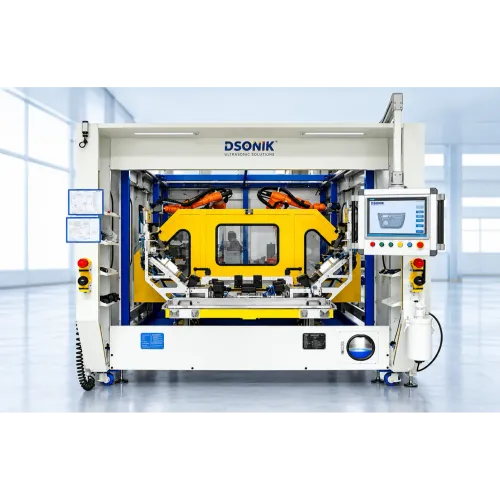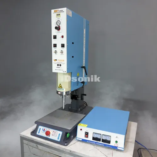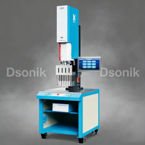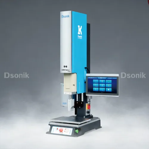

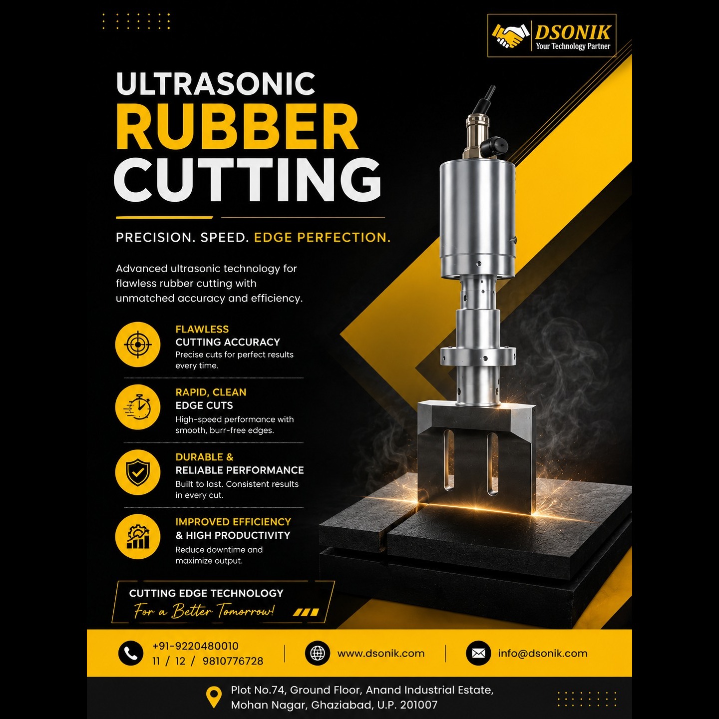
Ultrasonic cutting uses a blade that vibrates longitudinally at 20–40 kHz. These microscopic vibrations reduce cutting resistance, allowing rubber to be separated with less compression, stretching, and edge distortion than a stationary blade. The process is suitable for natural and synthetic rubber, tyre compounds, elastomers, hoses, sheets, profiles, and reinforced rubber products.
Key Advantages
• Produces clean, straight edges
• Requires less cutting force
• Reduces blade sticking and material drag
• Minimises deformation of soft components
• Cuts thick or tacky uncured rubber more easily
• Supports handheld, pneumatic-slide, servo-driven, and robotic systems
• Accommodates replaceable carbide tips for abrasive or reinforced materials
Recommended System Configuration
Application Suggested starting configuration
Thin rubber sheet, below about 5 mm 30–40 kHz, compact blade
General rubber profiles and sheets 20 or 30 kHz
Thick, soft or tacky rubber 20 kHz
Tyre tread or heavy compound 20 kHz, high-power rigid cutting horn
Fabric- or cord-reinforced rubber 20 kHz with carbide cutting tip
Automated contour cutting 30–40 kHz lightweight stack on robot/CNC
In general, 20 kHz is preferred for aggressive cutting, while 30–40 kHz systems are more compact, lighter, and quieter.
Typical Machine Arrangement
Ultrasonic generator → converter → booster → cutting horn/blade
The generator tracks the resonant frequency automatically. The booster controls vibration amplitude, and the sonotrode or cutting horn transfers this vibration to the blade. Commercial rubber-cutting systems are commonly available at 20, 30, 35, and 40 kHz.
Practical Starting Parameters
Use these values as initial development settings, not final production parameters:
• Frequency: Start at 20 kHz for most industrial rubber-cutting trials
• Generator power: Use approximately 1, 500–3, 000 W for medium to heavy sections
• Blade amplitude: Begin at a moderate setting, about 50–70% of rated system amplitude
• Cutting speed: Start at approximately 20–50 mm/s, then increase while monitoring edge quality and generator load
• Blade angle: Use an included cutting angle of approximately 15–30°
• Downward force: Apply only enough force to maintain penetration; excessive force can overload the horn
• Support: Use HDPE, polyurethane, wood composite, or another replaceable sacrificial cutting board
• Control: Use automatic frequency tracking and monitor power, overload, and amplitude
Some industrial generators provide 50–100% amplitude adjustment, automatic frequency tuning, and process monitoring.
Blade and Horn Design
For demanding rubber applications:
• Use a titanium horn or an engineered horn with a replaceable hardened or carbide blade
• Position the mounting flange near the vibration node
• Avoid sharp internal corners at blade slots and mounting transitions
• Design the blade for the intended longitudinal vibration mode
• Use modal FEA and tune the complete converter–booster–horn–blade assembly to the generator frequency
• Check for nearby bending or torsional modes, which can cause noise, uneven cuts, and blade failure
A long, thin blade should not simply be attached to a standard welding horn. The blade, joint, and horn must be engineered as a single resonant system.
Dsonik provides robust, reliable and long-lasting ultrasonic rubber cutting systems.